How Does a Skid Steer/Track Loader’s Hydraulic System Work? We Explain (Options Too)
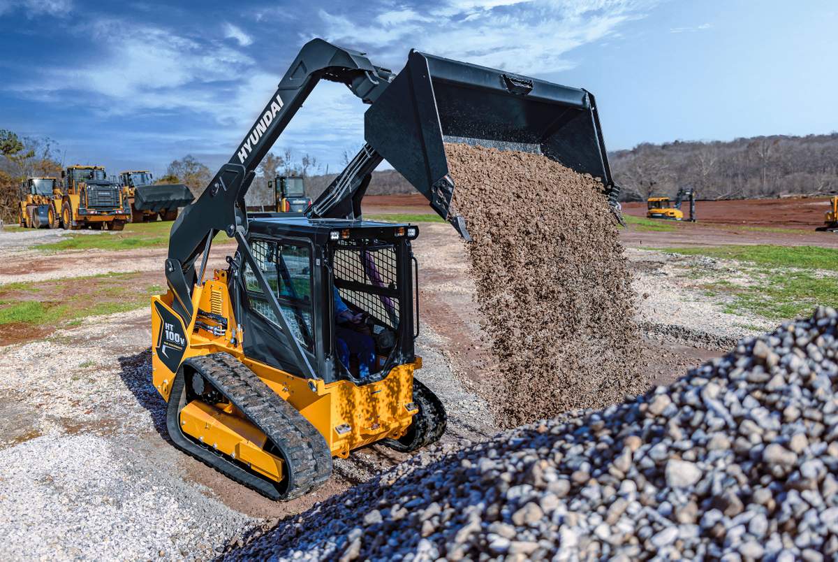
A skid steer has some moves. That zero-turn turning radius is tight. That lift height is legit. There’s the option to lay down tracks with an undercarriage via a compact track loader unit, increasing traction, flotation and applications. Then, there are just hundreds of attachments in its repertoire — auger, cold planer, nitro breaker, vibratory roller, brush cutter, the classic bucket and onward. A skid steer and its track loader cousin are two of the most powerful and versatile machine categories in the market (especially for their size), and these units have all the skill to shine in everything from plowing snow to trenching service lines. Quick question…
How Is This Possible?
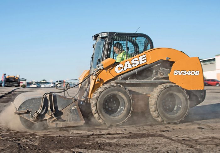
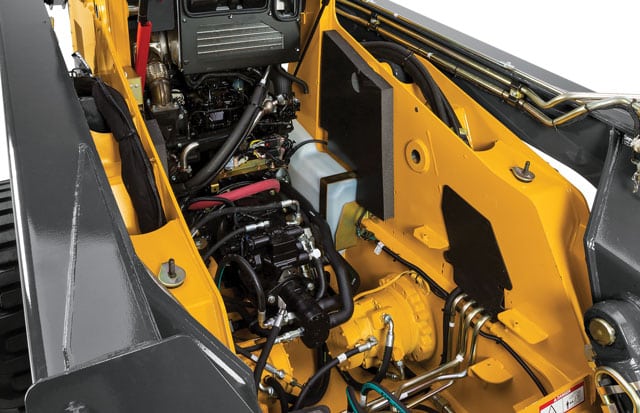
All of these extremely cool moves are made possible via a skid steer or track loader’s hydraulic system, which basically controls all the movement and power of both the unit and attachment using fluid mechanics and pressurized oil. A diesel engine creates the machine’s initial power using fuel, converting chemical energy into mechanical energy, but that energy is then transformed into fluid energy, harnessed in a closed loop hydraulic system that starts with hydraulic pumps attached to the diesel. These hydraulic pumps (often high-tech load sensing pumps) work with a system of hoses, reservoirs, filters, regulators, cylinders, directional control valves, actuators, motors and all the necessary electronics to generate and precisely control the pressure, flow and temperature of the hydraulic oil. This circulatory system is used to direct the power for drive operations, boom lifting and attachment usage.
“It’s the lifeblood of the machine, and the system that makes everything possible,” explains Jeff Jacobsmeyer, product manager at Case Construction Equipment. “At its most basic level, hydraulic oil is pumped and pushed throughout and directed through a variety of machine components that affect direction and force. Oil is used for its ability to withstand pressure and tolerate extremes in both cold and heat. And it all happens in a closed loop system, which is how pressures are maintained — remember from physics — a fluid cannot be compressed. We take mechanical horsepower from the rear of the engine crankshaft, convert it to hydraulic power that can be controlled and transferred into machine and attachment operations.”
Hydraulic operational systems have been the choice for most types of off-highway construction equipment for decades, capable of lifting heavier loads and creating impressive power. Hydraulics touch nearly every aspect of a skid steer and track loader. In fact, these units are often defined by their high hydraulic power to the attachment, operating gnarly implements like brush cutters and drop hammers.
But it’s not just attachments. It’s everything. The transmission runs on hydraulics. Most skid steers and track loaders run on hydrostatic transmissions, which means a hydrostatic pump sends oil with varying flows and pressure to move hydrostatic motors and drive system componentry. Capitalizing on hydrostatic operation vs. (let’s say) a gear transmission offers multiple advantages — steady power curve, infinitely variable speed control, lower power consumption and high power-to-weight ratio.
“Hydrostatic drive is really two pumps,” explains Buck Storlie, product manager at ASV. “One for the left track and one for the right track, driving the drive motors within the track system or the wheel and chain drive system on a skid steer loader. The beauty of hydrostatic drive is really infinite gearing, so you can shift that pump on or off in as little or as much flow as necessary.”
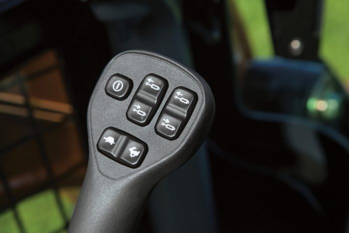
The majority of controls today work off hydraulics — electro-hydraulic and pilot-hydraulic — both of which are available in two operating patterns (H and ISO).
“Pilot controls use low pressure hydraulics to shift the valves spools,” says Nathan Ryan, global product manager at Manitou. “Electro-hydraulic controls rely on wires and sensors to achieve those same capabilities, and offer some adjustment in how the those controls respond. The two systems behind the joysticks electro-hydraulic and pilot-hydraulic each offer attractive attributes. Electro-hydraulic systems allow operators to adjust the response rates and switch patterns, while pilot controls deliver load feedback through the pilot lines and offer simpler problem diagnosis.”
It’s not just the drivetrain. A skid steer and track loader’s hydraulic system might use three or four pumps to push oil and power all the movements of the machine and attachment. These might be variable displacement or fix placement pumps, depending on what they do. One of these pumps is probably focused on supplying fluid power to the attachment. This part of the system is referred to as auxiliary hydraulics. Aux flow will have specifications like gallons per minute (gpm) and pressure (psi) that are important to understand and match when using an attachment like a broom or a breaker.
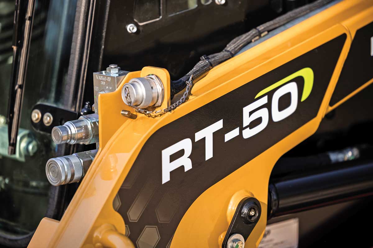
“Auxiliary hydraulics allow the connection of an external system, an attachment, to a skid steer or track loader’s main hydraulic system,” says Jerry Corder, product manager at Kubota Construction Equipment. “The connection to the attachment is made via the attachment’s hydraulic hoses to coupler ports on the skid steer or track loader. Once the hydraulic hoses of the attachment are connected to the coupler ports, you have added an auxiliary circuit in which the hydraulic oil from the main hydraulic system can flow to and return from. Pressurized hydraulic oil from the skid steer or track loader enters the auxiliary system — the attachment — via operator-directed control valves just as with the main system. As hydraulic pressure is directed to the attachment, the function of that attachment is enabled.”
What Are Your Auxiliary Flow Options?
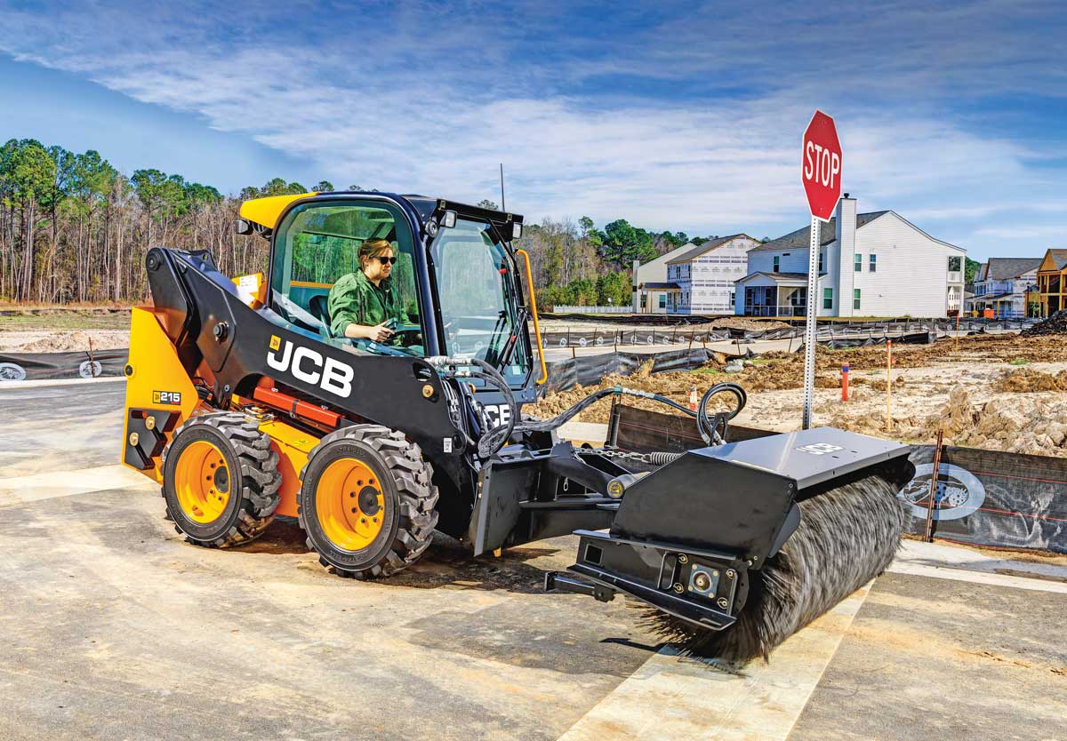
There aren’t a ton of choices when it comes to a skid steer or track loader’s hydraulic system. Your biggest choice is brand. Each purchase decision should include a thorough comparison of the unit’s hydraulic system, considering things like service, cooling, integration, automation, power, specs and onward. When it comes to hydraulic power to the attachment, there are some choices. Auxiliary hydraulics can come in standard or high flow, although certain manufacturers are marketing “super” or “enhanced” high-flow options. As mentioned, for attachment purposes, auxiliary hydraulic flow rates are measured in gpm and psi.
“It’s important that we understand hydraulic horsepower, too,” says Jacobsmeyer. “That’s really the marriage of flow and pressure to give you a rating for the machine. To calculate that, you multiply the psi of a machine by the gallons per minute, and then divide by 1,714. That equation gives you the hydraulic horsepower of the machine and will help you better match up with attachments and understand the true power of the machine and the attachment.”
On skid steers and track loaders, standard-flow auxiliary hydraulic systems range from 11 to 30 gpm with pressures topping off at 3,000 to 3,500 psi. High-flow auxiliary hydraulic systems range from 30 to 50 gpm with pressure capabilities up to 4,100 psi. At the top end of the spectrum, ASV’s RT-135F forestry CTL offers high flow as standard with a bonkers 50 gpm and a max system pressure of 4,060 psi. On the small end, the nimble ASV RT-25 CTL (the smallest in the industry) offers 11.3 gpm and a max system pressure of 3,000 psi.
Standard-flow systems will operate most categories of attachments, especially simpler and common implements like buckets, augers, pallet forks, trenchers and hammers. High-flow hydraulics can operate all those popular attachment categories too, plus more power-hungry tools like brush cutters, cold planers, rock saws and snowthrowers. The cost difference between standard and high flow (if it’s an option) can range from $2,000 to $5,000.
“On compact track loaders, I’d say 80 percent [of buyers] are taking it with high flow these days,” says Ethan Clowes, JCB product manager of skid steers, compact track loaders, wheel loaders and backhoe loaders. “When you go to skid steer loaders, it’s a bit less, probably talking about 30 or 40 percent. I believe it’s because what [those skid steer buyers are] doing is probably more loading, more dirt work. They’re after that productivity moving stuff. And they’re also after the value — the lower price of a wheeled machine — so then they’re also going to pick the valued options of standard flow.”
The attachment connection interface may also have some options. A manual quick-attach system requires getting out of the cab to move levers and secure pins for the attachment, while a hydraulic or power quick-connect system can be engaged from the cozy confines of the operator station. There are also standard- and high-flow coupler ports on a skid steer and track loader, and there may be some options with how those hoses connect.
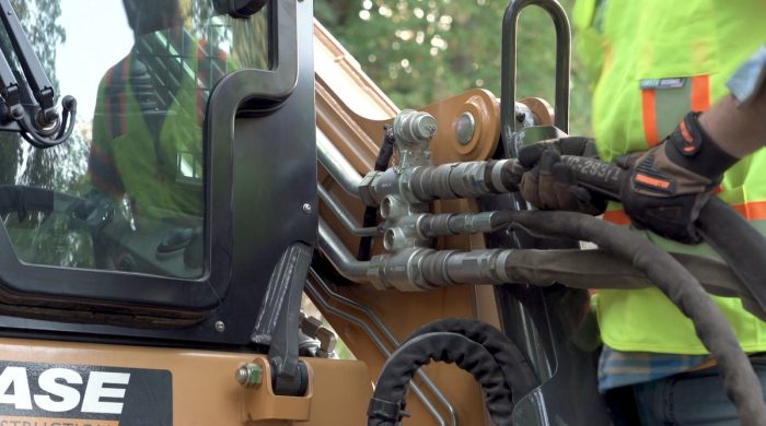
“The most popular option is flat-faced, quick-connect couplers,” says Corder. “These make connecting different attachments fast and convenient. An alternative to these is a screw-type coupler. They are far less convenient, but are more durable and secure and come with the benefit of running cooler since there is less constriction [more on cooling below].”
There may also be size options.
“We provide the capability to have 3/4-in. disconnects,” says Kevin Coleman, senior product application specialist at Cat. “We were talking about it having flow at 40 gallons a minute with our high-pressure system. You want that flow to move as freely as possible, so we offer that 3/4-in. quick disconnect but also still provide you that 1/2-in. quick disconnect for other tools that may not require it like a grapple bucket or multipurpose bucket. Most of our attachments, whether they be standard flow or high flow, connect through our 1/2-in. push-to-connect quick disconnects.”
Some attachments require electrical interaction and may also require a 14-pin connection for certain electrical functions and controls. “This will be dictated by the manufacturer of the attachment but is also important to consider when specifying a machine and matching it to attachments and hydraulics,” says Jacobsmeyer.
Cooling and Maintenance
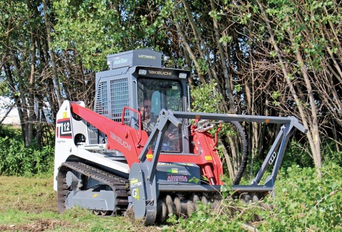
The hydraulics on a skid steer and compact track loader is a complex, powerful, hardworking system. Actually, it’s so powerful and hardworking that the hydraulic oil (the lifeblood!) can get pretty hot, so hydraulic cooling has become an increasingly important consideration when buying or renting a loader tool carrier. Some brands and third-party manufacturers even offer external hydraulic coolers that can mount on top of a unit to aid in cooling during intense attachment operations like brush cutting and cold planing (see photo above). Other brands are re-engineering units for aggressive hydraulic apps.
“Some of the key design criteria we’re chasing are things like larger line sizes and larger coolers,” explains Storlie. “If you think about 50 gpm of flow, we want to slow it down before we get into that cooler so it can go through there nice and slow and give the fan and the airflow time to exchange that heat. And then of course, large fans to speed up the airflow through that cooling system and hydraulic driven fans.”
The fan is definitely another area of inspection. Is it reversible? Those are great for dusty, debris heavy job environments. How is it powered? Because if it’s hydraulic…
“From day one, cooling has been part of our skid steer DNA,” says Coleman. “One of the ways we did that was we introduced our hydraulically driven cooling fan. That sounds very basic, but in reality, when you think about cooling, you want the cooling to occur somewhat independently of your engine speed. If you belt drive or direct drive a cooling fan right off the engine, then you must have your rpms as high as possible in order to get your maximum cooling airflow.”
Adequate cooling will go a long way in keeping your hydraulic system healthy, so also consider the radiator. There are other maintenance tips as well (beyond cooling). Keeping hydraulic systems in good working condition starts with ensuring they’re paired with the right attachments (hydraulic flow and pressure specifications). Hydraulic oil contamination issues are possible, and contaminated oil in an attachment can contaminate the host machine.
“We recommend before you switch attachments, you wipe those coupler faces because the main thing that’s going to go there is the seal between your attachments and the return filters,” explains Clowes. “That’s why the return filters are the first thing you change at 500 hours, because that’s when you’re going catch all that particular on its way back to the tank.”
To keep track of possible problems, hydraulic oil testing is available.
“We recommend, not only for hydraulic fluid but for other fluids as well, is what we call SOS sampling or SOS scheduled oil sampling,” says Coleman. “Our dealers have the capability to take that sample and analyze it and see any trends that are developing. If you schedule oil sampling and change your filters, our hydraulic oil should be able to go all the way up through 6,000 hours.”
Other daily or weekly hydraulic maintenance duties would include checking fluid levels, draining any fuel/water separators and looking for damaged lines, cylinders and hydraulic leaks around the machine. Also, make sure you’re using the right oil.
“There are different hydraulic oils,” notes Storlie. “The most common would be ISO 32, 46 and 68. Typically these standard grades can be interchanged based on ambient temp or operating conditions. I would just recommend folks take a look at their owner’s manual.”
That’s the biggest maintenance tip. Machine owners need to follow their manufacturer’s maintenance recommendations and timing.
Keith Gribbins is publisher of Compact Equipment.
Hydraulic Terminology
By Jerry Corder, Product Manager at Kubota Construction Equipment
- Hydraulic Oil Reservoir: Contains the hydraulic oil in a sufficient quantity to fill and pressurize the system.
- Hydraulic Oil Filter: Filters particulates from the oil as it enters the pump.
- Hydraulic Pump: A vehicle’s engine provides power to a hydraulic oil pump which generates the pressure and flow for the system to function.
- Pressure Regulator: Monitors the pressure generated by the pump and relieves excess pressure by diverting fluid back to the reservoir via a relief valve.
- Directional Control Valve: Enabled by the vehicle operator. These on/off valves enable and disable flow to hydraulic cylinders throughout the system to convert instruction from the operator into the work that the equipment performs.
- Hydraulic Cylinder: Hydraulic cylinders are the mechanical actuators of the system. They extend or retract depending on the flow received from the directional control valves. The function of these cylinders — whether a single cylinder or several in concert — enables the machine to move, lift, open and close buckets, etc.
- Hydraulic Oil Reservoir: Once the oil has moved through the various valves and cylinders, it returns to the reservoir and the cycle repeats.

