Plane as Day: Selecting the Right Flail
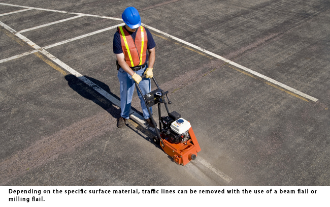
Initially introduced to the U.S. construction market nearly 35 years ago, small surface planers (sometimes referred to as scarifiers) have seen their popularity grow significantly. Routine surface planer applications now include trip-and-fall sidewalk projects, traffic line removal, surface coat removal and other tasks involving the removal of excess concrete or asphalt.
All surface planers share the same basic platform configuration. They are powered by a variety of sources, from gasoline and diesel engines to electric and even pneumatic motors. Some are manually propelled while others incorporate self-propelled drive systems. Power is normally transferred through a belt reduction connected to a high speed, rotating drum. This has become the standard design due to the belt’s ability to minimize the amount of destructive resonance transferred back to the power source. Manufacturers supply drums in a variety of diameters and widths, with width usually being the standard by which they are classified. Common cutting widths for surface planers are 8, 10 and 12 in.
Regardless of the manufacturer, drive configuration or drum width, all surface planers utilize a rotating drum loaded with rows of flails that impact directly against a target surface. This flailing action transfers a large amount of kinetic energy to strike against and subsequently remove material. The planing process itself is considered rather destructive and unrefined, in contrast to more controlled grinding with diamond discs or blades. How much material is actually removed with flails is dependent upon a number of factors, including drum/flail configuration, tensile strength of the material being removed and the machine’s travel speed.
Available Flails
Since the inception of surface planers, a wide number of flail configurations have been developed to help meet ever-increasing job applications. To make the selection process easier and reduce the levels of necessary inventory, many designs have been consolidated or eliminated over the years. Today, there are four basic flail configurations sold by most manufacturers. Each type is available in various industry standard diameters and thicknesses, with the specific tooth configuration being the designating factor for their respective names.
1. Star Flail — Star flails are stamped from high manganese content alloy steel and are through hardened for additional service life. The finish produced by star flails is normally a fine, broom-swept texture. Depending on the specific application, star flails will last one to three hours.
Typical applications:
A. Removal of coatings and encrusted materials.
B. Cleaning concrete and asphalt surfaces.
C. Light scarification prior to applying a new surface coating.
D. Steel deck de-scaling projects.
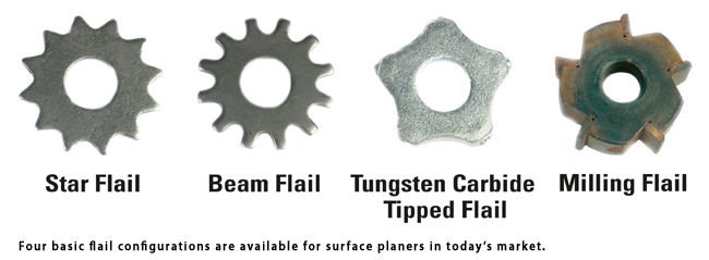
2. Beam Flail — Like star flails, beam flails are stamped from high manganese content alloy steel and are through hardened for added durability. The finish created is of a medium-coarse to coarse texture. Normal service life is one to three hours, depending on the application.
Typical applications:
A. Removal of thicker coatings and encrusted materials.
B. Medium-duty concrete and asphalt removal.
C. Removal of traffic lines.
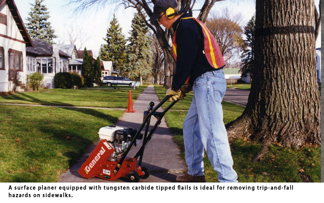
3. Tungsten Carbide Tipped Flail — These flails feature extremely durable tungsten carbide inserts brazed in a perimeter configuration around an alloy steel body. Popular configurations are five- or six-sided. The higher quality construction delivers maximum performance and return on investment for most material removal projects. Tungsten carbide tipped flails produce a medium to coarse surface texture. The flails can last up to 250 hours.
Typical applications:
A. Heavy-duty concrete and asphalt removal.
B. Removal of trip-and-fall hazards.
C. Concrete and asphalt grooving projects.
4. Milling Flail — Milling flails incorporate rectangular tungsten carbide inserts that are also brazed around the perimeter of an alloy steel body. The configuration is very similar to that of standard machine tool cutters, making milling flails directional in nature. This requires them to be operated in an “upcut” or “climb cut” mode. When using most manually propelled planers, the machine should be pulled toward the operator. If the planer is pushed forward, the flails will “down cut,” causing wear on the back side of the inserts and significantly decreasing the service life of the flails. With proper operation, milling flails can last up to 30 hours, depending on the specific application.
Typical applications:
A. Removal of traffic lines from concrete and asphalt surfaces.
B. Removal of membrane type materials from concrete surfaces.
Choose and Use Wisely
Flails are the heart and soul of the material removal process. They define how fast the material is removed and the corresponding surface finish. Proper selection, operation and maintenance will allow for faster material removal and maximize the return on investment.
Dennis Von Ruden is president of General Equipment Co., based in Owatonna, Minn.
Comments are closed here.